
Design of the dual chiral framework for dynamic circular dichroism modulation
Generally, 3D structures with twisting features in the propagation direction such as helices are highly desirable to realize strong optical chirality. As shown in the Fig. 1a, a left-handed helix can be stretched and compressed to change the chiroptical response of the structure. However, if one wants to completely reverse the structure from left-handed to right-handed, the system needs to overcome a giant energy barrier. Here, we propose a universal strategy to fully address this problem, namely the dual chiral framework. Its basic principle is to achieve continuous modulation of CD response through the constructive and destructive effects of two chiral structures (Fig. 1b). The chirality of helical structures can be described by helicity (H)32:
$$H=\frac{1}{n}{\sum }_{i=1}^{n}{\phi }_{i}{d}_{i},$$
(1)
where n is the number of chiral units, ϕi is the torsion angle of the structure, di is the distance along the spiral axis. For the simplest case, which is a structure composed of two chiral units, its helicity (H2) can be expressed as:
$${H}_{2}=\frac{1}{2}({\phi }_{1}{d}_{1}+{\phi }_{2}{d}_{2}).$$
(2)

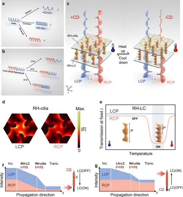
a, b Functional design for dynamic optical chirality. A helix structure (a) can be stretched and contracted to alter its chiroptical response. If one wants to completely reverse the structure from left-handed (LH) to right-handed (RH), the system needs to overcome a giant energy barrier. For a dual chiral framework (b), dynamic modulation between positive and negative values can be achieved by matching the zero points of their helicity (H). c Schematic of the framework made by nano-cilia metasurface integrated with thermoresponsive cholesteric liquid crystal (LC). The dual chiral structures enable the amplification, elimination, and reversal of chiroptical response at different temperatures. d Electric field distributions of RH-cilia. The RH-cilia exhibits stronger plasmonic resonance to LCP, resulting in lower transmittance of LCP compared to RCP. e Schematic of the chiral transmission of LC versus temperature at fixed wavelength (λ). The thermoresponsive LC pitch (P) will shrink after being heated, leading to a blueshift of the CPL photonic bandgap and the subsequent change in transmission. When the bandgap shifts, the transmission initially decreases, reaches and maintains a minimum, and finally increases. The gray background marks the “ON” state of the LC. f, g Illustration of different combinations of two chiral elements to obtain a tunable and dual chiral framework. In (f) the nano-cilia and LC with opposite chiroptical response (+CD and −CD) enables the elimination and reversal of CD. In comparison, in (g) nano-cilia and LC with both positive chiroptical response (+CD and +CD) can achieve the amplification of CD.
When the torsion angle is greater than zero, the structure can be considered right-handed, otherwise it is left-handed. Therefore, the key to achieve chiroptical reversal can be represented by the following equation:
$${\phi }_{1}{d}_{1}+{\phi }_{2}{d}_{2}=0,$$
(3)
which means finding the zero chiral point of the framework. Equation 3 demonstrates the connection between two units. However, the above equations do not provide a direct answer for high-precision in-situ chiroptical reversal. We have solved this problem through a design that combines stationary and dynamic helical structures. Specifically, we first design a stationary nano-cilia structure to determine the operating wavelength and bandwidth of the overall framework, and then combine it with scalable liquid crystal helix to achieve chiroptical reversal and states control.
The schematic of the cholesteric liquid-crystal embedded nano-cilia photonic structure is shown in Fig. 1c. The incident CPL interacts with the cholesteric LC and the nano-cilia successively. Both structures have different transmittance for right- and left-handed CPL, thus forming a dual chiroptical response. Functionally, the nano-cilia structure provides a giant static CD value, and the LC layer provides tunability to the framework. Here, CD is defined as
$${CD}=({T}_{{RCP}}-{T}_{{LCP}})/({T}_{{RCP}}+{T}_{{LCP}}),$$
(4)
where TRCP and TLCP denotes transmittance of right- and left-handed CPL respectively. The framework shown in the Fig. 1c is composed of right-handed nano-cilia (RH-cilia) and right-handed LC (RH-LC). At low temperatures, the chiroptical response of the framework is mainly determined by RH-cilia, resulting in a positive CD. At a certain high temperature, RH-LC shows strong modulation effect on RCP light, and the combined chiroptical response causes the reversal of CD.
To achieve chiroptical regulation, the response wavelength of these two elements should match with each other. The optical response range of liquid crystals are generally within the visible wavelengths, while constructing chiral nano-kirigami structures in this range becomes a critical challenge as the 3D deformation ability of the structure weakens as the size of the structure decreases. A main reason is that former closed-loop designs33,34,35 typically result in interference between adjacent elements, making it challenging to downsize the nano-kirigami structures. To address this problem, we adopted a nano-cilia design36, an open-loop structure that enabled us to achieve a nanoscale kirigami structure with optical responses in the visible wavelengths.
The nano-cilia metasurface is constructed on a gold/quartz substrate. Figure 1d shows the electric field distributions of RH-cilia. The cantilever of cilia structure spirals in the direction of light propagation, thus having a modulation effect on CPL. The RH-cilia exhibits stronger plasmonic resonance to LCP, resulting in lower transmittance of LCP compared to RCP. Therefore, according to the definition of CD, RH-cilia shows a positive CD value and LH-cilia shows a negative CD value. The cholesteric LC was then bonded on the back of the quartz substrate. The helical organization of LC molecules causes a chiral photonic bandgap centered at λcenter = naveP, where nave is the average refractive index of the cholesteric LC, and P is the helical pitch. The CPL component with the same handedness as that of the chiral LC structure will be sufficiently reflected within the bandgap, while the opposite CPL will transmit for all wavelengths37. For a certain wavelength, the dynamic modulation in CPL transmission could be obtained by a tunable pitch P. Figure 1e qualitatively depicts the variation of TLCP and TRCP as a function of the temperature in the RH cholesteric LC. A higher temperature leads to a shorter pitch, thus a blueshift of the bandgap. As a result, TRCP decreases to nearly zero (ON state) and then increases back to nearly 100% (OFF state) during heating, while TLCP is unaffected. In such a case, the CD value of the RH-LC approaches zero (OFF state) or takes a negative maximum (ON state) when the incident wavelength is outside or within the bandgap, correspondingly. In contrast, an LH-LC exhibits a tunable CD value from nearly zero to a positive extreme.
The CD response of the framework is manifested as the transmission difference between LCP and RCP. In our framework designs, nano-cilia and LC with opposite chiroptical response (+CD and -CD) enables the elimination or reversal of CD, while nano-cilia and LC with both positive chiroptical response (+CD and +CD) can achieve amplification of CD. Figure 1f, g show two implementation examples of the dual chiral framework. For the RH-cilia with +CD, by combining the right-handed LC (RH-LC) with tunable -CD (Fig. 1f), the TRCP decreases from higher than TLCP to lower than TLCP. Specifically, the incident CPL interacts with the cholesteric LC and the nano-cilia successively. RH-LC only has the ability to modulate TRCP, while RH-cilia has a positive CD response itself. When RCP light passes through the RH-LC, the light intensity decreased (or maintained) when LC is on (or off), while the LCP light intensity does not change. Therefore, when the RCP transmittance of RH-LC approaches 100% at the off state, there is no modulation effect on TRCP in the RH-LC region and the framework maintains a totally positive CD response due to the RH-cilia. In comparison, when the RCP transmittance of RH-LC approaches 0% at the on state, TRCP is less than TLCP in the RH-LC region, thus achieving a negative CD in the RH-LC region. In such a case, the overall CD value after passing through the nano-cilia could be negative, zero, or positive, dependent on the situation of LC.
As for the combination of RH-cilia and LH-LC (Fig. 1g), the TLCP decreases in the LCP photonic bandgap, while TRCP remains the same. Therefore, the difference of TLCP and TRCP enlarges, amplifying the positive CD response.
Fabrication and spectral performance of the chiral nano-cilia metasurface
The detailed fabrication process of nano-cilia is shown in Fig. 2a. The two-dimensional (2D) nano-cilia pattern is directly formed by high-dose focused ion beam (FIB) milling. After that, wet-etching process is applied by HF solution (HF: H2O = 1:4) for 45 s. The HF solution etches beneath SiO2 through Au slits, and the arms of nano-cilia are released from the substrate. Then, low-dose global ion beam (GIB) irradiation is employed to induce tensile stress for final deformation, transforming the originally 2D planar nanostructure to 3D twisted nano-cilia structure. To create a chiroptical response in visible wavelengths, the nano-cilia structures are designed with a periodicity of p = 500 nm, a central cylinder radius with r = 130 nm, and an arm width of w = 60 nm (Fig. 2b). Three suspended arms of nano-cilia are initially planar (Fig. 2c) and then deformed by introducing inner stress through GIB irradiation38 (Fig. 2d). These twisted structures provide a physical basis for chiroptical response.

a The preparation process of nano-cilia metasurface. The nano-cilia structure is realized by a nano-kirigami process: a high dose focused ion beam (FIB) is used for film cutting, and then a low dose global ion beam (GIB) is used for structure twisting. b Schematic of nano-cilia units. The units are designed with a periodicity of p = 500 nm, a central cylinder radius with r = 130 nm, and an arm width of w = 60 nm. c, d Side-view SEM images of 2D and 3D state of nano-cilia metasurface. Scale bars: 500 nm. e Experimental vertical displacement of the nano-cilia as a function of ion dose. Error bars represent standard deviation (SD) of three independent experiments (n = 3). f SEM images of nano-cilia metasurface with different displacement. Scale bar: 500 nm. The initial and final images are top views, and the intermediate images are oblique views with an angle of 52°. g Calculated CD spectra of 3D deformed RH/LH-cilia. h, i Experimental transmission and CD spectra of 3D deformed RH/LH-cilia under LCP and RCP excitation.
Quantitatively, the ion beam irradiation can be described by the dosage of ion beam. For FIB milling, a high dosage of >50 pC/µm2 is employed to cut the 2D nano-patterns. Then, the deformation of the nano-cilia is realized by globally irradiating the entire metasurface with a relative low dose of 0.1−5 pC/µm2. The main mechanism of the nano-deformation is to use the residual stress induced by the gallium ion collisions with the gold thin films. Figure 2e shows the deformation height of the nano-cilia as a function of the ion dose. When the gold nanofilm is irradiated by ion beams, some gold atoms are knocked out, causing surrounding atoms to aggregate towards the vacancies, resulting in tensile stress close to the surface of the film. Meanwhile, the inner atoms are subjected to compressive stress due to the influence of implanted gallium ions. These two types of stresses occur within a thickness of ~20 nm on the top layer of the gold film8, which further drives the elastic deformation of bottom layer. In such a case, the residual stress will cause the structure to bend globally under the guidance of the initial topographies until new equilibrium morphologies are reached (Fig. 2f).
Figure 2g shows simulated CD spectra of 3D deformed RH- and LH-cilia. Due to the vertical deformation of three metallic nano-cilia arms, the mirror symmetry was broken and a resonance peak appears at 690 nm (see detailed analysis in Supplementary Information Note S1). The transmissions of LCP and RCP show great difference, which causes a narrow CD peak at this wavelength. The resonance peak and intensity are mainly decided by the handedness-dependent excitation of electric dipole mode at the tip of the nano-cilia (see detailed analysis in Supplementary Information Note S2). Figure 2h, i present the experimental transmission and CD spectra of 3D deformed RH- and LH-cilia, with a maximum CD of 0.46 at 690 nm. These results well match with theoretical simulations in terms of resonance wavelength, while the differences in resonance intensity and linewidth are mainly due to structural deviations during the fabrication process. The implantation of Ga+ ions during FIB milling and irradiation introduced optical loss, which broadened the resonance peak of nano-cilia. Meanwhile, incomplete wet etching process resulted in residual SiO2. The capillary forces during the drying process of the wet etching may lead to the imperfect deformation of some of the suspended nano-cilia arms. Nevertheless, the structure remains stable once fabricated. The deformation of nano Au arms under ion induced stress does not change with temperature (see spectral stability of nano-cilia metasurface in Supplementary Information Note S3).
The deformation mechanism of nano-cilia is to utilize the residual stress generated by the collision between ions and gold films, which creates a stress difference between the surface and inner layer of the gold film, leading to the structural distortion. This deformation trend is unidirectional, therefore reversible optical modulation and CD reversal cannot be achieved. To address this issue, we introduced another chiral material to participate in CPL modulation, namely cholesteric LC.
Optical properties of cholesteric liquid crystal
The preparation of cholesteric LC was achieved by mixing the thermoresponsive RH/LH chiral dopants R811/S811 with nematic liquid crystal E7 (Fig. 3a) at a carefully designed ratio39. After injected into a cell, the LC molecules assemble to uniform standing helices with a pitch length P and parallel directors at both surfaces (Methods). Due to P determining the wavelength of photonic bandgap, thicker LC has more pitches with the same photonic bandgap (Fig. 3b). The helical pitch becomes shorter in response to heat stimulation, and the resultant bandgap blueshifts. As a result, the cholesteric LC texture appears dark gray at 24 °C and red at 34 °C (Fig. 3c), since their reflection are within the infrared and red range, respectively.

a Molecular structures of nematic LC mixture E7, and thermoresponsive RH/LH chiral dopant R811/S811. b The calculated relation between the cholesteric LC pitch number and the center wavelength of the CPL photonic bandgap. The center wavelength is calculated by λcenter = naveP = naveD/N, where nave is the average of the ordinary and the extraordinary refractive indices of the cholesteric LC, D is the cell gap, P is the pitch, and N is the pitch number expressed by N = D/P. c Reflection spectra of 7.5 μm LH-LC at 24.0 °C (gray line) and 34.0 °C (red line). Inset: Microscopic reflection images of the 7.5 μm LH-LC at 24.0 °C and 34.0 °C. White arrows denote the polarization of the crossed polarizers. Scale bars: 100 μm. d The shift of bandgaps for the 4.0-µm (cyan) and the 7.5-µm (green) LH-LCs. Each bar denotes a stable state, whose upper and lower boundaries mark the photonic band gap edges, and the horizontal location represents the temperature. e, f Transmission spectra of 4.0 μm and 7.5 μm thick LH-LC under LCP excitation at different temperatures. The arrows indicate the blueshift of bandgap when the temperature increases. g Dynamic transmission of 4.0 μm and 7.5 μm thick LH-LC under LCP excitation at wavelength of 690 nm.
The surface anchoring of the cell restricts the LC pitches to the discrete set P = D/N, where D is the cell gap (i.e., sample thickness) and the pitch number N must be an integer or a half integer. Therefore, the photonic bandgap is tuned quasi-continuously (Fig. 3d), and the cell of D = 7.5 µm allows more stable intermediate states and smaller intervals than that of D = 4.0 µm (see detailed analysis in Supplementary Information Note S4). The in-situ transmission spectra of the thermoresponsive cholesteric LCs with different D are shown in Fig. 3e, f. Due to the larger pitch number, the transmission bandgap edge of thicker samples is steeper. The bandgaps demonstrate a distinct blueshift with increasing temperature (Fig. 3d). Figure 3g illustrates the detailed process of transmission recovering at 690 nm as the bandgap shifts away. In the cell of D = 7.5 µm, since the heat-driven regulation in the pitch could take smaller intervals, TLCP changes in a smoother way, instead of a drastic change (see detailed analysis of dynamic response in Supplementary Information Note S5). Notably, the LC cell gap provides a way to adjust the thermal sensitivity of the dual chiral framework.
Dynamic CD modulation enabled by the dual chiral framework
We integrate cholesteric LC onto the back of the quartz substrate loaded with nano-cilia to form the dual chiral framework. A homemade optical characterization setup was employed to measure the dynamic CD modulation capability of the sample (Fig. 4a). A halogen light served as the light source, emitting a light beam that illuminated the fabricated sample. The light beam passed through a linear polarizer (LP) and a quarter-wave plate (QWP) to generate CPL. Subsequently, the light beam was focused on the sample by using a 20 × objective lens. The sample was placed on a heating stage and the CD modulation process was recorded by a spectrometer.

a The optical characterization setup. Inset shows the dual chiral framework of RH nano-cilia with LH- or RH-LC. b Static CD spectra of frameworks with LH-/RH-LC at temperature of 30.4 °C. c Dynamic CD modulation of frameworks with LH-/RH-LC as a function of temperature. d, e Detailed CD modulation process of frameworks with different LC thicknesses. The framework integrated with RH-LC (d) demonstrates the process of CD reduction and reversal. The framework integrated with LH-LC (e) demonstrates the process of CD amplification.
The static CD spectra of dual chiral frameworks based on RH-cilia are shown in Fig. 4b. For a framework with LH-LC, TLCP decreases due to the Bragg reflection. Therefore, the difference between the original high TRCP and the low TLCP of nano-cilia structure is further enlarged (see optical transmission spectrum in Supplementary Information Note S6), leading to a CD enhancement from 0.46 to 0.84. Conversely, for a framework with the RH-LC, TRCP decreases from a value higher than TLCP to a value lower than TLCP. So, the initial positive CD will be modulated from 0.46 to a negative CD of −0.76. LCs have the ability to reduce the transmittance of one CPL from its initial value to nearly 0. In such a case, the transmitted RCP and LCP light at the entrance of the RH-cilia are different, resulting in asymmetry between the maximum and minimum CD of the two frameworks. Meanwhile, the changes in RCP or LCP transmittance will simultaneously affect both the numerator and denominator of the CD equation (Eq. 4), resulting in a small difference in absolute CD values between the two frameworks.
The above CD features are the optical response of the frameworks at a fixed temperature, which can be further modulated by heating the cholesteric LC. As is shown in Fig. 4c, we illustrate the dynamic CD modulation process of the dual chiral frameworks in a single wavelength perspective (λ = 690 nm). For the framework with LH-LC (Fig. 4c, blue curve), the blueshift of the CPL photonic bandgap causes the dynamic modulation of the TLCP. The TLCP gradually decreases when the CPL photonic bandgap includes 690 nm, and recovers when the CPL photonic bandgap moves out. Therefore, the CD of the framework is amplified at first and then recovered. Different modulation processes happen to the framework with the RH-LC (Fig. 4c, orange curve). The TRCP is modulated from initially higher than TLCP and finally to lower than TLCP. Three chiroptical response states occur during this process: positive CD, non-chirality, and negative CD. The extremum of CD occurs at difference temperatures for the framework with different chiral LC. This is due to slight differences in the temperature response of LC with different chiral dopants R811/S811. We measured the transmission of two different cholesteric LCs at 690 nm as a function of temperature (see Supplementary Information Note S7). The results indicate that the cholesteric LCs have different transmission valley, which is consistent with Fig. 4c.
As we have mentioned above, the thickness of LC will affect the sensitivity of CD modulation. We heated the device with a uniform heating rate and recorded the CD at different temperatures in situ (Fig. 4d, e). The framework with a 4.0 μm-thick LC has a faster thermal response, while a 7.5 μm-thick LC gives the slower changing of CD (see detailed analysis in Supplementary Information Note S5). We can choose appropriate device thickness according to the requirement of application scenarios.
Thermally tunable CPL metalens
It can be seen from the above experiments that embedding different types of cholesteric LC on the same nano-cilia metasurface can realize different types of chiroptical regulation. Furthermore, we can also combine different types of nano-cilia on the same LC to achieve light field regulation of CPL. Here, we designed a thermally tunable CPL focusing metalens by utilizing the giant CD modulation ability of the dual chiral framework. Figure 5a depict the schematic of the metalens. Considering a beam of LCP light incident on the structures, RH-cilia has a lower LCP transmittance compared to LH-cilia. By designing a metasurface with a circular transmittance distribution (Fig. 5b, c), chiroptical focusing can be achieved. Furthermore, thermoresponsive cholesteric LC can adjust the intensity of incident LCP, eliminating the circular transmittance distribution, allowing the metalens to switch between focused and non-focused states.

a Schematic of thermally tunable metalens. b Schematic of the metalens design, with the RH-cilia (red) forming the fine ring and the rest being LH-cilia (black). By designing a metasurface with a circular transmittance distribution, chiroptical focusing can be achieved. c Illustration of the metalens’ first order concentric ring. d The SEM image of the metalens’ first order concentric ring. RH-cilia structures are framed by red dashed line. Scale bar: 2 μm. e Detailed SEM image of the LH- and RH-cilia in the metalens. RH-cilia structures are framed by red dashed line, and LH-cilia structures are framed by black dashed line. Scale bar: 500 nm. f Experimental transmission spectrum of LH- and RH-cilia structures under LCP excitation. Orange line shows the CDlens spectrum. g Cross-sectional focal point intensity plots along the x-direction. h Cross-sectional focal point intensity plots along the z-direction. i−l Simulated and experimental focal point image. m Dynamic focusing switch of the metalens. The CDlens first decreases and then increases with temperature, during which the metalens initially loses its CPL focusing ability and then refocuses again. Insets show the optical image of the focal position. The metalens exhibits a reversed response to circular and linearly polarized light.
Experimentally, we constructed 37,440 nano-cilia units with an area of 80 μm × 80 μm, which employs two types of nano-cilia structures to form several concentric rings on LH-LC. Figure 5d shows the SEM image of the first order ring. These nano-cilia units are arranged in a hexagonal pattern, with the RH-cilia forming fine rings and the rest being LH-cilia (Fig. 5e). The width of the rings is only one pixel, and each pixel of the metalens contains only one nano-cilia unit. The position of each ring is determined by using the Rayleigh–Sommerfeld diffraction method40,41,42. These rings consist of LH- and RH-cilia have different transmittance for incident CPL, which enable the focusing of light. Here, we introduce CDlens to evaluate the optical response of the CPL metalens:
$${{CD}}_{{lens}}=({T}_{{LHc}}-{T}_{{RHc}})/({T}_{{LHc}}+{T}_{{RHc}}),$$
(5)
where TLHc and TRHc are the transmittance of LH- and RH-cilia. Figure 5f shows the LCP transmittance of LH- and RH-cilia. The LH-cilia has a transmittance of 55% at 690 nm, while the RH-cilia has a transmittance of only 23%, resulting in a CDlens of 0.41.
Theoretical simulation of the intensity distribution of the designed metalens in the focal region is shown in Fig. 5g, h. The focal length is designed to be 50 μm. The metalens is able to achieve subwavelength focusing performance in the x-y plane as the full width at half maximum (FWHM) is 450 nm, corresponding to 0.65λ at the incident wavelength of 690 nm. Meanwhile, a high resolution of 3.3 μm (4.7λ) along the z-direction is also achieved. The corresponding experimental demonstration (Fig. 5g, h, orange line) show a high resolution of 582 nm (0.84 λ) and 3.8 μm (5.5λ) in the x-y plane and along the z-direction, respectively.
We compared the simulated and experimental focal point image on x-y and x-z plane (Fig. 5i–l), the well-matched results confirm the high accuracy of the nano-kirigami method. This achievement signifies the successful development of a tunable CPL metalens, demonstrating its adaptability and functionality in response to thermal conditions. Considering the focal length and numerical aperture (NA) of the metalens can be flexibly designed and controlled, and the small size (80 μm × 80 μm) allows convenient integration of such a metalens on the facet of an optical fiber that has a typical diameter of >100 μm. Our thermally tunable metalens can be used as an optical modulator to encode 0 and 1 for optical communications. Meanwhile, the high spatial resolution allows the use of our metalens in a fiber optic endoscope to achieve miniaturized size and high-resolution optical imaging for broad applications43,44.
The dynamic modulation process of the CPL metalens is shown in Fig. 5m. For an incident LCP light at the wavelength of 690 nm, the metalens exhibited focusing ability owing to the different transmission of two types of nano-cilia at 25 °C. The center wavelength of the LCP Bragg reflection band shifted to 690 nm when the metalens was heated to 35 °C, and the focusing function was disabled due to the elimination of CDlens. When the temperature reaches 41 °C, the Bragg reflection band blue shifted to a much shorter wavelengths, away from 690 nm, so the metalens regained its focusing ability. As can be seen, this metalens can undergo continuous changes in focused and defocused states within the range of 25 °C to 41 °C. Interestingly, our metalens exhibits a reversed response to linearly and circular polarized light: it focuses incident linearly polarized light when the LC is activated, but not when deactivated (Fig. 5m inset, see Supplementary Information Note S8 for details). Given its imaging capability, this metalens shows potential for multispectral imaging of polarization-sensitive objects.
In the above experiments, we utilized the difference in transmittance between LH- and RH-cilia to achieve different focusing effects for different polarized light. Another interesting combination is to arrange cilia with different rotation angles for geometric phase modulation, which enables circular polarization switching (see Supplementary Information Note S9). In our framework design, the twist of the liquid crystal is responsible for dynamic modulation, while the static cilia structure can be designed and arranged in multiple dimensions such as the number, length, width, and height of the arms, allowing our device able to not only modulate CD response, but also achieve rich applications.


